Zombie 133 5709

Re: Zombie 133 5709
Done it several times over the years and there are enough cars in my garage that could be used as reference 
I own some of the odd Jensen 
-
americanjohn

- Posts: 69
- Joined: Wed Dec 11, 2013 12:09 pm
- Location: Düsseldorf, Germany
Re: Zombie 133 5709
Suspension
Some significant progress since my last post. Re-installed the front suspension using the method described in the Tech Tips (4 threaded rods). Sure glad I stumbled over that article, I took them out with a single spring compressor and was chewing my nails about having to use that sketchy tool to put them back in. Those 4 rods do get warm when you crank up those big coils! While the springs were out I had them lowered 1” because I thought it would look better. A couple months later I read that the US models were raised 1” to meet safety standards so we’re Euro spec now.
Also had the rear axle checked out. All was fine so we didn’t rebuild, just put in new seals. Went back in surprisingly easy, but the leaf springs aren’t compressed enough so can’t fit the lower shock bolts yet. The springs looked almost new so I’m wondering if the previous owner had them rebuilt or replaced. They’ll probably settle once there is more weight in the back.
Then installed all new brake lines, bending them and putting flanges / fittings on turned out to be quite the project.
- Attachments
-
- 8FBA73EA-80CF-48A5-B479-0578E7A9AD2F.jpeg (80.81 KiB) Viewed 3646 times
-
- 18544457-5AEC-4DC5-9A18-DE30D212B8F8.jpeg (61.47 KiB) Viewed 3646 times
-
americanjohn
- Posts: 69
- Joined: Wed Dec 11, 2013 12:09 pm
- Location: Düsseldorf, Germany
Re: Zombie 133 5709
Engine Bay
Spent several days fitting insulation to the engine compartment and then a layer of aluminum heat shield on top of it. It was oddly satisfying, but not sure I’d want to do another one.
Also took the opportunity to address an issue which killed me during disassembly. There is a drip tray under the cowl vent which is welded to the firewall. Unfortunately, it makes removal of the windshield wiper assembly a killer. I had discussed this with Mark I a while back and decided to modify. I removed the steel drip tray, cooky fiberglass pieces and the spacer between the firewall and blower motor. This allows 1) for easier access to the wiper assembly and 2) moves the whole blower and duct backwards, which gives 1”-1.5” more room at the back of the engine. The downside of this is that the water from above needs to go somewhere. I decided to fabricate a removable drip tray which mounts underneath the cowl vent using its mounting bolts. This has a separate hose which drains down along the AC condensation. As far as I can tell, the fiberglass pieces were there to allow fresh air (and water) into the cowl and over to the vacuum-operated door on the firewall into the interior. As I wanted to maintain the fresh air circuit, I also fabricated a reverse scoop which accepts a hose that runs down to the grill on the RH side of the car. Not sure this will give the same flow, we’ll see later on.
- Attachments
-
- E4BA0ADE-756A-4634-BB69-6ABDDCEB21BE.jpeg (212.59 KiB) Viewed 3646 times
-
- 0F7EA3D4-32C7-4933-A9A9-6F777F2122E5.jpeg (76.38 KiB) Viewed 3646 times
-
- 547D0E8B-37CD-4FA5-B80E-40413FA13B94.jpeg (73.56 KiB) Viewed 3646 times
-
- first version in back was too tall for wiper drive
- 97E1D085-A1F3-408A-92FA-8136209E27AB.jpeg (84.72 KiB) Viewed 3646 times
-
- 53B0272F-D2C1-4137-819F-F53BC198D1A9.jpeg (108.18 KiB) Viewed 3646 times
-
- 39D211AE-F542-44AF-91BE-80EE21C208A0.jpeg (118.99 KiB) Viewed 3646 times
-
americanjohn
- Posts: 69
- Joined: Wed Dec 11, 2013 12:09 pm
- Location: Düsseldorf, Germany
Re: Zombie 133 5709
Coming close to stuffing the 440 back in, although the 727 may have to go first separately. My rolling hoist can only handle 500 kg at full extension. Firewall is almost finished, except for the replacement of the kooky vacuum-operated AC switch. I actually got the old one working, but it was rough and I had no desire to replace any time soon.
- Attachments
-
- 1F126FA9-326A-44D6-A155-305BFC786D58.jpeg (130.35 KiB) Viewed 3502 times
-
- 768357DD-4F9A-48CF-B4F9-FD1ADB7317B4.jpeg (128.55 KiB) Viewed 3502 times
-
americanjohn
- Posts: 69
- Joined: Wed Dec 11, 2013 12:09 pm
- Location: Düsseldorf, Germany
Re: Zombie 133 5709
Electrical Challenges
I’m knee deep in wiring right now and stumbled upon several issues where I was hoping someone could help out.
How are these 5 heavy wires (P, NY, PB, UW, BG) on the rear harness (right next to the 9 pin connector) hooked up to the facia harness? Looking at the old harness it appears as though they were unused, but this seems strange as the power has to go out back somehow, for example the demist on the rear glass (BG) or the fuel flap (NY).
Also trying to figure out what this thingamajig is, looks like either a clean power supply for the radio or maybe the shaver outlet. It was mounted to the left of the transmission opening on the inside firewall
Update: fairly certain that this is a power supply for the radio. I deleted this as the rebuilt the LearJet has an uprated power supply.
- Attachments
-
- B9B39F32-8741-45BE-BB28-9F5E1599926C.jpeg (94.85 KiB) Viewed 3408 times
-
- 67911642-5D49-4817-8874-DFDFD6539155.jpeg (105.92 KiB) Viewed 3408 times
Last edited by americanjohn on Tue Nov 30, 2021 11:45 pm, edited 1 time in total.
-
americanjohn
- Posts: 69
- Joined: Wed Dec 11, 2013 12:09 pm
- Location: Düsseldorf, Germany
Re: Zombie 133 5709
Figured out that the heavy wires in the rear harness are inside the LH door harness, they go through the large, clear 9 pin plug and then exit a few inches later so they can connect to the rear harness. Interesting if you read the little round symbols on the wiring diagram
- Attachments
-
- B0813569-0C6E-495D-AD76-C0C118593764.jpeg (129.93 KiB) Viewed 3383 times
-
americanjohn
- Posts: 69
- Joined: Wed Dec 11, 2013 12:09 pm
- Location: Düsseldorf, Germany
Re: Zombie 133 5709
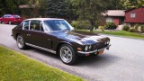
Nice to see some light after 8 years of darkness!
- Attachments
-
- B94231B9-9DBE-46A4-900D-A42A2108A438.jpeg (107.4 KiB) Viewed 3386 times
-
- BEDA4C11-C86F-4421-BBA4-10BE960F876A.jpeg (134.71 KiB) Viewed 3386 times
-
americanjohn
- Posts: 69
- Joined: Wed Dec 11, 2013 12:09 pm
- Location: Düsseldorf, Germany
Re: Zombie 133 5709
Engine/ Transmission (lessons learned)
Finally got around to stuffing the 440 back in. Had some time off so I figured I’d have a go of it by myself (lesson 1). Original plan was to fit both the engine and transmission as a unit, but had to abandon this as it was too heavy for the engine crane and too long to attain the proper angle. Managed to get the motor in after a couple hours and celebrated my success for day one (prematurely). The transmission turned out to be more of a challenge. Jacked up the front of the car and slid the transmission underneath, then lifted it into place with the engine crane. The big surprise came when I determined that the cut out in the frame for the transmission is narrower on the bottom then the top (lesson 2). That small 3/4” offset in width makes all the difference in the world. I had originally measured from the top in the hole for the transmission tunnel where it is wider. In the end I was able to twist it and lift it into place diagonally - a process which took twice as much time and muscle power as installing the engine. A few weeks later I stumbled upon an interesting sentence in section A.5 of the workshop manual: “It is possible to remove the gear box only on the Mk II cars”. (Lesson 3)
Finally got around to stuffing the 440 back in. Had some time off so I figured I’d have a go of it by myself (lesson 1). Original plan was to fit both the engine and transmission as a unit, but had to abandon this as it was too heavy for the engine crane and too long to attain the proper angle. Managed to get the motor in after a couple hours and celebrated my success for day one (prematurely). The transmission turned out to be more of a challenge. Jacked up the front of the car and slid the transmission underneath, then lifted it into place with the engine crane. The big surprise came when I determined that the cut out in the frame for the transmission is narrower on the bottom then the top (lesson 2). That small 3/4” offset in width makes all the difference in the world. I had originally measured from the top in the hole for the transmission tunnel where it is wider. In the end I was able to twist it and lift it into place diagonally - a process which took twice as much time and muscle power as installing the engine. A few weeks later I stumbled upon an interesting sentence in section A.5 of the workshop manual: “It is possible to remove the gear box only on the Mk II cars”. (Lesson 3)
- Attachments
-
- 05955583-08F1-4653-BA44-C72A22B980B9.jpeg (159.05 KiB) Viewed 2796 times
-
- 96C1BB56-FC94-4555-A30D-0B745321F9EE.jpeg (129.57 KiB) Viewed 2796 times

Re: Zombie 133 5709
Reading your post I wondered how you used a crane to lift the gearbox till I saw your photo.
My preference is to remove engine and box as one but install them separately with the gearbox first, Ive done it both ways and just find this easiest. Also remove the crankshaft pulley and this makes clearance of the front crossmember easier.
Anyway looks like a fantastic job you are doing there.
My preference is to remove engine and box as one but install them separately with the gearbox first, Ive done it both ways and just find this easiest. Also remove the crankshaft pulley and this makes clearance of the front crossmember easier.
Anyway looks like a fantastic job you are doing there.
Dave Pearce
Oily Rag Classics
Jensen FF 119/133
Jensen FF 119/182
Jensen Interceptor III 128/4430
Oily Rag Classics
Jensen FF 119/133
Jensen FF 119/182
Jensen Interceptor III 128/4430
-
americanjohn
- Posts: 69
- Joined: Wed Dec 11, 2013 12:09 pm
- Location: Düsseldorf, Germany
Re: Zombie 133 5709
Thanks a lot, Dave. It’s been a slow process as I’ve done most everything myself, but that was my choice of “therapy“. The forum has saved me many times during this process.
Had a friend help me pull the engine and transmission out as a unit using a forklift 7 years ago. That’s how I wanted to put them back in, but the crane wasn’t up to the job. It definitely would’ve been better to fit the transmission first, then the engine (as noted very discretely in the workshop manual). The cut outs in the tubular frame led me to the false conclusion that the transmission could come out/go in separately. At first I didn’t notice that the cut outs are angled with the top being slightly narrower then the bottom, that’s where the trouble came from.
Fortunately, the windshield is still out and I was just able to pass the lifting strap down through the hole and right up against the HVAC box. After quite a bit of fumbling about / manhandling it finally went into place. Only casualty was the new neutral safety switch, which was bent up during the process.
- Attachments
-
- 9F84D301-6D1F-4B67-85E0-73401697BCE4.jpeg (136.13 KiB) Viewed 2652 times
Last edited by americanjohn on Fri Dec 10, 2021 6:59 am, edited 1 time in total.
-
americanjohn
- Posts: 69
- Joined: Wed Dec 11, 2013 12:09 pm
- Location: Düsseldorf, Germany
Re: Zombie 133 5709
Ride Height?
So I ran into an issue that is somewhat strange. After I refitted the front and rear springs, the car is sitting about 3 inches too high - even now that the boat anchor RB is back in. Sitting that high in the back has made it impossible to connect the rear shocks to the axle for a hook up the drive/prop shaft.
I actually had the front coils shortened by 1 inch to match the euro spec cars. The rear leaf springs were in excellent shape (they may have been replaced sometime) so I just cleaned, greased thoroughly and re-covered with that nasty wrapping tape.
I figure the springs have expanded as they’ve been out of the car for so long with no load. Hopefully they will settle in. Has anyone else run into this issue?
- Attachments
-
- 841FA042-3D54-4559-AC5F-B6274C16A711.jpeg (116.24 KiB) Viewed 2651 times
-
slotcarone
- Posts: 1666
- Joined: Sun Aug 29, 2010 1:38 pm
Re: Zombie 133 5709
Your car looks beautiful so far! The springs will not gain new life because they were out of the car. Is the car actually sitting on the ground in that last picture? I does not look like it is. The rear spring front and rear mounting bolts should only be put in loosely until the weight of the fully assembled car is on them and then tightened up. Are you sure the front coils are sitting in the correct spot in the lower seat? That would make it sit too high.
1972 Interceptor III
133-5612
133-5612
-
americanjohn
- Posts: 69
- Joined: Wed Dec 11, 2013 12:09 pm
- Location: Düsseldorf, Germany
Re: Zombie 133 5709
Thanks! After closer inspection I realized the picture above shows the car after my transmission follies where the front end was still partially jacked up. The rear end is on the ground. Actually, the problem is more evident in the rear. The rear shackle bolts and spring eye / mounting bolts as well as the U bolts holding the axle to the springs are still loose. It’s odd because I did not disassemble the rear leaf springs (they were fine). Sitting about 3 inches too high in back. Are by chance the springs meant to go in one direction only? I measured in the distance from the eye to the center pin is the same on both ends.
Even with the car on the ground the front is still around 1.5 - 2 inches too high. The upper and lower wishbone nuts are still loose. I’m sure I have the front coils in properly. I seated the top first and then swung the lower wishbone up and made sure the bottom was seated properly as well.
Even with the car on the ground the front is still around 1.5 - 2 inches too high. The upper and lower wishbone nuts are still loose. I’m sure I have the front coils in properly. I seated the top first and then swung the lower wishbone up and made sure the bottom was seated properly as well.
- Attachments
-
- 0D7CFBFA-686C-45AC-B81B-F1EEB0802109.jpeg (90.31 KiB) Viewed 2620 times
-
- C5921657-993B-47AB-B8D0-F783D2DF7742.jpeg (63.37 KiB) Viewed 2620 times
-
slotcarone
- Posts: 1666
- Joined: Sun Aug 29, 2010 1:38 pm
Re: Zombie 133 5709
The rear springs have different bushings on the ends. the front has a steel sleeve and the rear has two rubber bushings. That should tell you which end is which. Stil a lot of weight missing from your car. Put it together completely first before worrying about the height.
1972 Interceptor III
133-5612
133-5612
Re: Zombie 133 5709
As slotcarone said lots of weight still missing, but you can load up the boot with something heavy like sand or gravel then stand in the boot and jump up and down. This will help settle the springs, I may have done this myself 

Dave Pearce
Oily Rag Classics
Jensen FF 119/133
Jensen FF 119/182
Jensen Interceptor III 128/4430
Oily Rag Classics
Jensen FF 119/133
Jensen FF 119/182
Jensen Interceptor III 128/4430